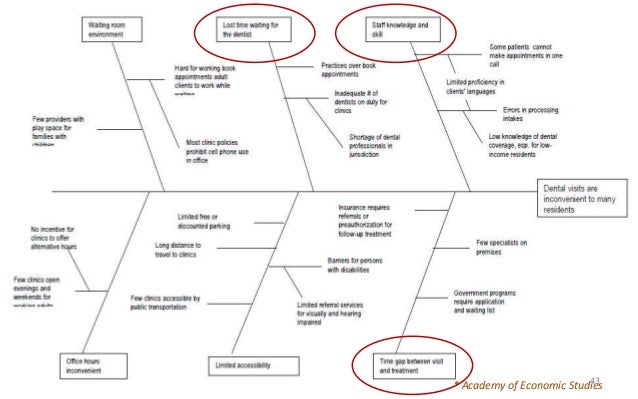
The possible cause with the highest priority will be investigated further and then dealt with.

This process is continued until no more possible causes are mentioned.These secondary causes are entered as branches in the Fishbone Diagram. The participants also mention possible secondary causes.All the listed causes are included in the Fishbone Diagram. No comments may be made on each other’s causes. Each participant mentions one possible cause for the problem and states in which category the problem belongs.The problem, in which the analysis is to be performed, is written at the top of the paper.It starts with a large piece of paper on which a fishbone is drawn.įrom there the following steps come up for discussion: The Fishbone Diagram takes shape by following a number of steps. This category investigates whether possible causes can be found in the work method are the work processes adequate how are the cooperative arrangements organized, how do employees and departments communicate with each other, etc.? Details of the Fishbone Diagram There may be problems with the materials, raw materials and consumables and semi-finished products what is the quality, how much do we need, are the materials resistant to external influences, how long will they last, etc.? Methods This concerns causes related to the functioning of machines, tools, installations and computers have the correct machines been used, are the machines safe enough, do the machines meet the requirements, are they reliable, etc.? Materials This concerns all causes that are created by human actions is there good communication, do people understand their assignments, are the employees sufficiently involved, experienced and trained, etc.? Machines Subsequently, each category is branched into secondary causes.

These root causes are subdivided into four categories. On the right-hand side of the Fishbone Diagram the problems are described and on the left-hand side the possible root causes are denominated. The Fishbone Diagram makes a distinction between cause and result. Today, the Ishikawa diagram is also used in other sectors. Actually, the diagram was intended for production processes and its accompanying quality control. To obtain insight into these factors, he designed a simple graphical tool, in which the potential root causes are represented in an orderly fashion.Īs this root cause analysis model resembles a fishbone, the Ishikawa diagram is, also called the Cause and Effect Analysis. Do you want unlimited and ad-free access? Find out more


 0 kommentar(er)
